H-beams, H-section columns, roof beams and crane girders
7-AXIS · GMAW
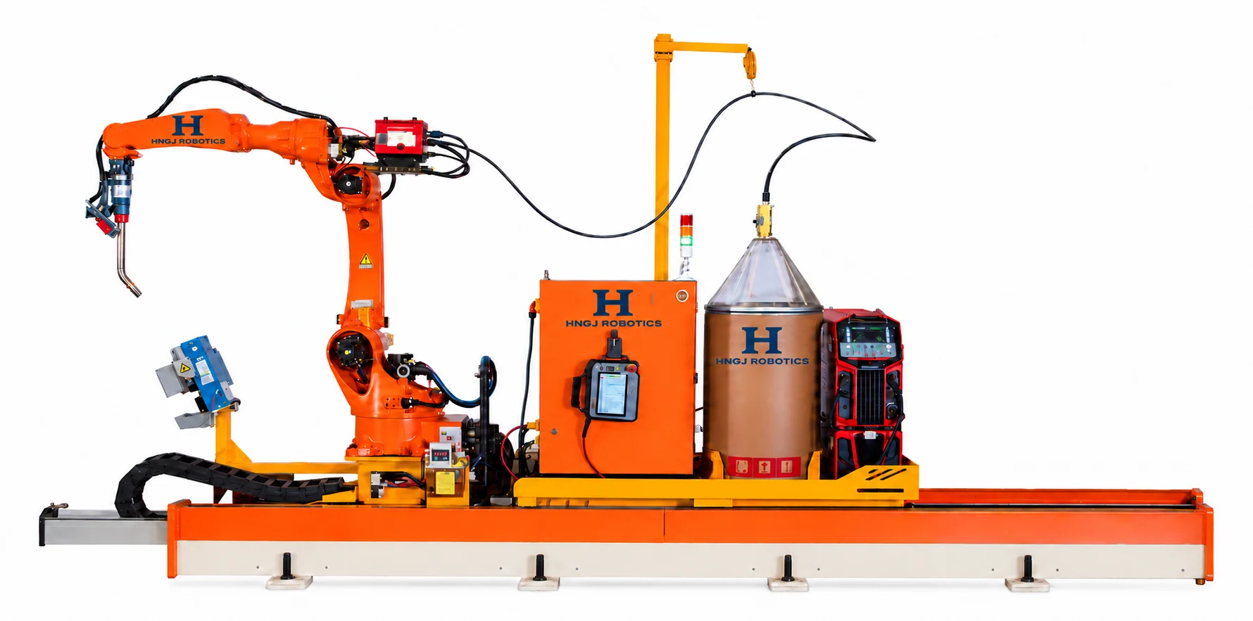
7-axis rail-guided welding
A six-axis robot on a floor-mounted travel rail brings a wider working range to structural-steel welding. Suitable applications include H-columns, roof beams, crane girders and brackets.
Robotic welding12 m reference rail
Enquire about this equipment01 / PRODUCT OVERVIEW
How this equipment works.
A six-axis welding robot mounted on a floor travel axis extends the reachable welding area along the component. The arrangement suits long, relatively open steel members whose welds can be accessed from the planned rail position.
Import STEP or IFC models, or reconstruct a tack-welded part from a 3D scan. The workflow extracts welds, matches process data and checks the planned path for collisions before precise seam scanning and welding. Part preparation and scan confirmation remain operator tasks.
Find the fit for your parts.
Curved beams with accessible welds
Cross-shaped columns
Box columns at accessible assembly stages
Steel stairs
Purlin support plates, brackets and corbels
Before choosing a configuration
Review rail-side access, workpiece width, stiffener spacing, torch clearance and weld position. A long rail does not make every surface accessible in one setup.
03 / PROCESS & CONFIGURATION
Designed for the task.
- Import STEP / IFC models or reconstruct parts from a 3D scan.
- Automatic seam extraction, path planning and collision checks.
- Laser localization and precision seam scanning.
- Multilayer, multipass welding for suitable thick-plate joints.
TECHNICAL OVERVIEW
Key specifications
| Workstation axes | 6 robot axes + 1 travel axis |
|---|---|
| Reference rail length | 12 m |
| Workpiece width | ≤1.4 m |
| Robot reach | 2014 mm |
| Robot repeatability | ±0.08 mm |
Configuration reference: HNGJ Global. Parameters apply to the referenced configuration. Final scope is confirmed in the technical agreement. Robot-only figures are identified separately.
APPLICATION & PROCESS
Confirm the welding fit.
Shared process guidance for the seven- and eight-axis GMAW workstations.
| Workpiece material | Carbon steel and low-alloy steel; stainless steel requires application validation. |
|---|---|
| Welding method | Gas metal arc welding (GMAW) |
| Reference plate thickness | 5–30 mm |
| Welding positions | PA flat, PB horizontal-vertical fillet, PG vertical-down |
| Shielding gas options | 80% Ar + 20% CO₂; 100% CO₂; 95% Ar + 5% O₂ |
| Solid wire diameter | Ø1.0 / Ø1.2 / Ø1.6 mm |
| Flux-cored wire diameter | Ø1.2 mm |
Gas and wire are selected for the material and qualified welding procedure. Stainless steel suitability requires validation of surface reflection, scanning and arc tracking.
Access matters as much as reach.
Flat-web components must allow camera scanning and torch approach. Reference rib clearances are 150 mm for flat welding and 450 mm for vertical welding, subject to torch geometry and surrounding plate height.
View processes, clearances & jointsSupplemental equipment configuration
| Robot | QJR6-2000, six-axis, upright mounting; 2,000 mm arm radius |
|---|---|
| Control & vision | Welding control software V1.0; air-cooled robot vision |
| Torch package | 500MR water-cooled torch and torch-cleaning package |
| Welding power source | Dex2 500MPR water-cooled pulsed source with water tank and wire feeder |
| Rail | 12,000 mm total length; 10,630 mm effective carriage travel |
| Operator cabinet | Industrial PC, display, mouse and keyboard |
This is a separate reference configuration from the supplementary sheet. Rail length and robot reach may differ from the catalog configuration above; the final equipment list and working envelope are confirmed in the technical agreement.
A useful brief gets a clearer proposal.
Send material grade and thickness, maximum part dimensions and weight, joint or cutting details, batch size, target output and the installation country. Describe the current process and the bottleneck you want to resolve.
04 / AFTER-SALES SUPPORT
Support throughout operation.
Build a service plan around your equipment, operators and installation location. The following items can be included in the agreed project scope.
Installation & commissioning
Agree checks for the robot installation, external axes where fitted, fixtures, power, gas and extraction. Commissioning reviews coordinate references and sample welds against the agreed process.
Operator training
Training can include job preparation, the supported programming or scanning method, process selection, weld inspection and routine restart procedures.
Care & maintenance
Robot and rail checks cover reference positions, lubrication, torch cleaning, wire feeding and camera calibration. Operator support should include model import, scan review and recovery from interrupted jobs.
Troubleshooting & spare parts
Share the equipment model, fault code, operating conditions and relevant photos when requesting support. Diagnosis, replacement parts and any on-site visit are coordinated for the installed configuration and project location.
Warranty & service arrangements
Warranty duration, consumable coverage, software support and response arrangements are confirmed in the project agreement. Overseas on-site work, travel costs and parts delivery are agreed for the destination.
Related equipment
Robotic welding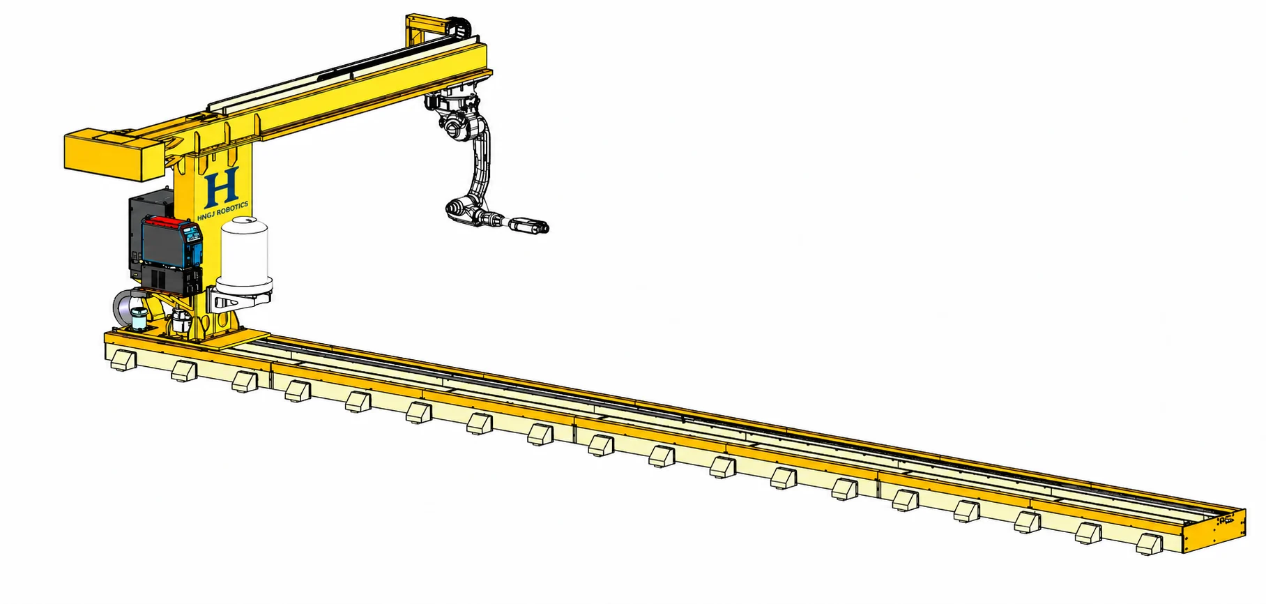
8-axis cantilever welding
A suspended robot and two travel axes for flexible cell layouts.
Robotic welding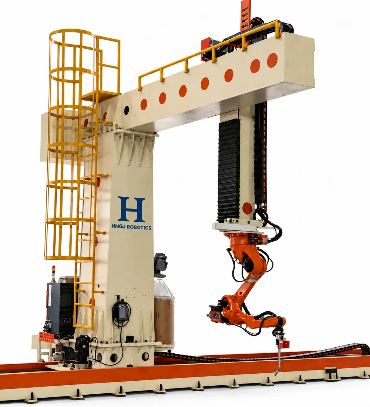
9-axis cantilever welding
Reach further with three external motion axes for larger components.
Robotic welding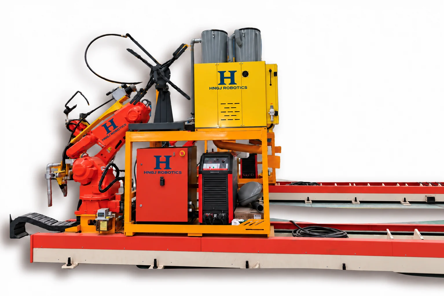
7-axis submerged arc welding
Groove scanning and multipass welding for thick structural steel.
Your next step starts with a conversation.
Tell us what you make. Let’s define the right equipment configuration.