Arc-start retry
Helps improve arc initiation when contamination is present at the starting point; suitable for multilayer, multipass work.

Review materials, process functions, torch access and camera-scannable joints for relatively open steel structures.
| Workpiece material | Carbon steel and low-alloy steel; stainless steel requires application validation. |
|---|---|
| Welding method | Gas metal arc welding (GMAW) |
| Reference plate thickness | 5–30 mm |
| Welding positions | PA flat, PB horizontal-vertical fillet, PG vertical-down |
| Shielding gas options | 80% Ar + 20% CO₂; 100% CO₂; 95% Ar + 5% O₂ |
| Solid wire diameter | Ø1.0 / Ø1.2 / Ø1.6 mm |
| Flux-cored wire diameter | Ø1.2 mm |
Typical parts include H-section columns, roof and crane beams, corbels, purlin supports, bridge diaphragms, ship sub-assemblies and transformer oil tanks. Joint access must be reviewed for each part.
Supported seam geometries include straight and planar polygonal fillets, vertical fillets, continuous wrap-around welds, lap welds, planar circular-arc seams and multilayer/multipass seams. The reference requires flat web plates.
Galvanized parts are excluded because of reflection; aluminum alloy is excluded because arc tracking is not supported. Reflective stainless steel is outside the supported reference scope. Non-mirror stainless steel requires validation of scanning, arc tracking and welding for its actual surface condition before selection.
Availability depends on the selected software package and validated welding procedure.
Helps improve arc initiation when contamination is present at the starting point; suitable for multilayer, multipass work.
Sinusoidal, triangular, L-shaped, oblique sinusoidal, pendulum and circular-arc patterns.
For components requiring reduced welding distortion. Currently limited to straight seams.
The operator can manually return to the stopping point and resume the interrupted job.
Restarts with a backward overlap to fill the crater left by an interrupted arc.
Laser positioning identifies corners and automatically adjusts torch orientation.
Connects multiple seams into a continuous welding sequence to reduce stop/start joints.
Plans torch orientation at fan-shaped areas with collision checks for seam alignment.
Corrects lateral and longitudinal deviations during welding and supports multiple weaving patterns.
Automatically generates paths and supports arc tracking on the bottom layer.
Uses the wire for position finding to compensate for positioning deviations before welding.
Automatic collision checks assess the space for camera positioning and torch approach.
Empirical reference only, based on a 135° water-cooled torch with a 100 mm extended gooseneck. For the vertical-welding reference, the torch is at 0° to the web plate. Surrounding rib and flange heights affect the required clearance; confirm it for the actual torch, fixture and component.
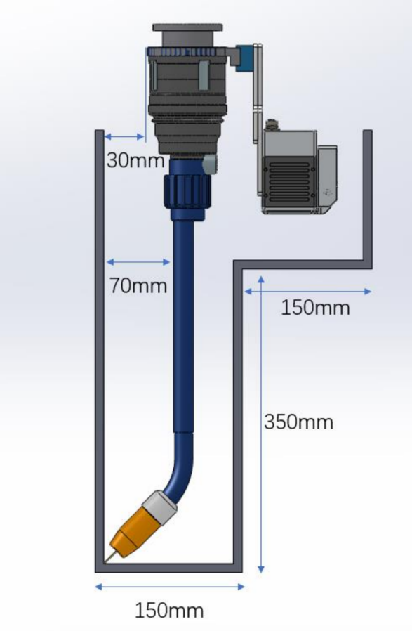
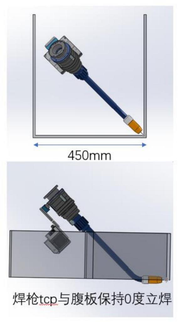
Minimum dimensions below apply to the illustrated reference geometries. Expand each joint for its scan mode and limits.
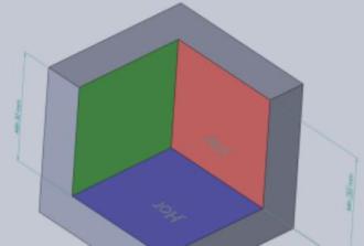
Static scan of the triple intersection
Each plane width ≥30 mm
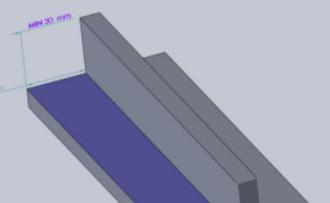
Static scan of the intersection edge endpoint
Each plane width ≥30 mm
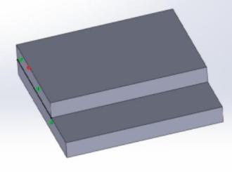
Static endpoint scan
Flat plate thickness ≥8 mm; base plate width ≥30 mm
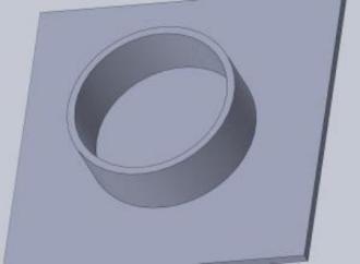
Robot-guided full-circumference scan
Radius ≥100 mm; wall height ≥18 mm; base plate width ≥15 mm. Multilayer/multipass supported; intermittent welding not supported.
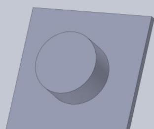
Robot-guided full-circumference scan
Radius ≥100 mm; cylinder wall height ≥18 mm; base plate width ≥15 mm. Multilayer/multipass supported; intermittent welding not supported.
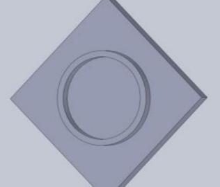
Robot-guided full-circumference scan
Radius ≥100 mm; cylindrical wall height ≥12 mm and thickness ≥15 mm; base plate width ≥12 mm
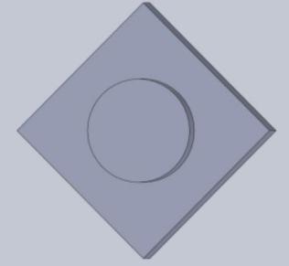
Robot-guided full-circumference scan
Radius ≥100 mm; solid cylinder height ≥12 mm; base plate width ≥15 mm
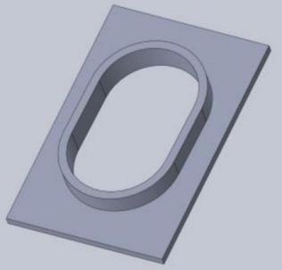
Robot-guided closed-path scan
Radius ≥100 mm; cylindrical wall height ≥18 mm; base plate width ≥15 mm. Multilayer/multipass supported; intermittent welding not supported.
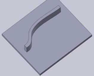
Robot-guided full free-form path scan
Arc radius ≥50 mm; curved plate height ≥18 mm; base plate width ≥15 mm. Multilayer/multipass supported; intermittent welding not supported.
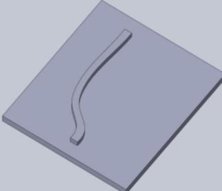
Robot-guided full free-form path scan
Arc radius ≥50 mm; curved plate height ≥12 mm; base plate width ≥15 mm; free-form vertical plate thickness ≥15 mm
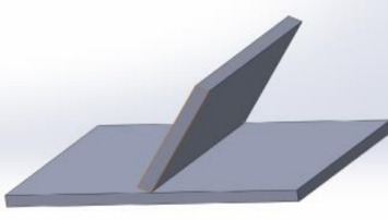
Static endpoint scan
Included angle 45°–135°; each plane width ≥30 mm
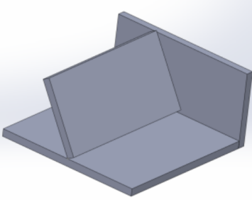
Static endpoint scan
Included angle 45°–135°; each plane width ≥30 mm